目录
概述
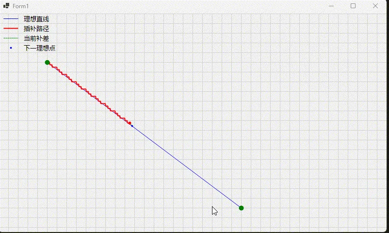
在本文中,我们将详细讲解如何使用C#的GDI+实现直线插补运动的模拟。上图展示了一个基本的直线插补示意图,我们将通过代码来实现这个效果。
基础知识
直线插补是数控系统中的一个基本概念,它是指在两点之间通过算法计算出中间点的过程,使运动呈现连续平滑的状态。
代码实现
C#using System.Drawing.Drawing2D;
using Timer = System.Windows.Forms.Timer;

namespace WinFormsApp2
{
    public partial class Form1 : Form
    {
        private const int GRID_SIZE = 20;  // 网格大小
        private const int STEP_SIZE = 5;   // 步进大小
        private Timer animationTimer;
        private Point startPoint;
        private Point endPoint;
        private Point currentPoint;
        private Point nextPoint;  // 下一个目标点
        private List<Point> interpolationPoints;
        private bool isAnimating = false;

        public Form1()
        {
            InitializeComponent();


            this.SetStyle(
                ControlStyles.DoubleBuffer |
                ControlStyles.UserPaint |
                ControlStyles.AllPaintingInWmPaint,
                true);

            startPoint = new Point(100, 100);
            endPoint = new Point(500, 400);
            currentPoint = startPoint;
            interpolationPoints = new List<Point> { startPoint };

            animationTimer = new Timer();
            animationTimer.Interval = 100;
            animationTimer.Tick += AnimationTimer_Tick;

            this.Paint += LineInterpolationForm_Paint;
            this.KeyPress += LineInterpolationForm_KeyPress;
        }


        private void LineInterpolationForm_KeyPress(object sender, KeyPressEventArgs e)
        {
            if (e.KeyChar == ' ')
            {
                if (!isAnimating)
                {
                    currentPoint = startPoint;
                    interpolationPoints.Clear();
                    interpolationPoints.Add(startPoint);
                    isAnimating = true;
                    animationTimer.Start();
                }
                else
                {
                    isAnimating = false;
                    animationTimer.Stop();
                }
            }
        }

        private Point CalculateNextIdealPoint()
        {
            // 计算下一个X位置
            int nextX = currentPoint.X + STEP_SIZE;

            // 确保不超过终点
            if (nextX > endPoint.X)
                nextX = endPoint.X;

            // 计算理想直线上的Y值
            double slope = (double)(endPoint.Y - startPoint.Y) / (endPoint.X - startPoint.X);
            int nextY = (int)(startPoint.Y + slope * (nextX - startPoint.X));

            return new Point(nextX, nextY);
        }

        private void AnimationTimer_Tick(object sender, EventArgs e)
        {
            if (currentPoint.X >= endPoint.X && currentPoint.Y >= endPoint.Y)
            {
                animationTimer.Stop();
                isAnimating = false;
                return;
            }

            // 计算理想的下一个点
            nextPoint = CalculateNextIdealPoint();

            // 决定移动方向
            Point previousPoint = currentPoint;

            if (Math.Abs(currentPoint.Y - nextPoint.Y) > Math.Abs(currentPoint.X - nextPoint.X))
            {
                // Y方向误差大,优先移动Y
                if (currentPoint.Y < nextPoint.Y)
                    currentPoint.Y += STEP_SIZE;
                else
                    currentPoint.Y -= STEP_SIZE;
            }
            else
            {
                // X方向优先
                currentPoint.X += STEP_SIZE;
            }

            interpolationPoints.Add(currentPoint);
            this.Invalidate();
        }

        private void LineInterpolationForm_Paint(object sender, PaintEventArgs e)
        {
            Graphics g = e.Graphics;
            g.SmoothingMode = System.Drawing.Drawing2D.SmoothingMode.AntiAlias;

            // 绘制网格
            DrawGrid(g);

            // 绘制理想直线
            using (Pen idealLinePen = new Pen(Color.Blue, 1))
            {
                g.DrawLine(idealLinePen, startPoint, endPoint);
            }

            // 绘制插补路径
            if (interpolationPoints.Count > 1)
            {
                using (Pen interpolationPen = new Pen(Color.Red, 2))
                {
                    for (int i = 1; i < interpolationPoints.Count; i++)
                    {
                        g.DrawLine(interpolationPen,
                            interpolationPoints[i - 1],
                            interpolationPoints[i]);
                    }
                }

                // 绘制当前步进的补差线
                if (isAnimating && interpolationPoints.Count > 0)
                {
                    using (Pen errorPen = new Pen(Color.Green, 1))
                    {
                        errorPen.DashStyle = System.Drawing.Drawing2D.DashStyle.Dash;

                        // 只绘制当前点到理想下一点的补差线
                        Point currentIdealPoint = CalculateNextIdealPoint();
                        g.DrawLine(errorPen, currentPoint, currentIdealPoint);
                    }
                }
            }

            // 绘制起点和终点
            using (SolidBrush brush = new SolidBrush(Color.Green))
            {
                g.FillEllipse(brush, startPoint.X - 5, startPoint.Y - 5, 10, 10);
                g.FillEllipse(brush, endPoint.X - 5, endPoint.Y - 5, 10, 10);
            }

            // 绘制当前点
            using (SolidBrush brush = new SolidBrush(Color.Red))
            {
                g.FillEllipse(brush, currentPoint.X - 3, currentPoint.Y - 3, 6, 6);
            }

            // 如果正在运动,绘制下一个理想点
            if (isAnimating)
            {
                using (SolidBrush brush = new SolidBrush(Color.Blue))
                {
                    Point idealNext = CalculateNextIdealPoint();
                    g.FillEllipse(brush, idealNext.X - 2, idealNext.Y - 2, 4, 4);
                }
            }

            DrawLegend(g);
        }

        private void DrawLegend(Graphics g)
        {
            int legendX = 10;
            int legendY = 10;
            int legendSpacing = 20;

            // 理想直线图例
            g.DrawLine(new Pen(Color.Blue, 1), legendX, legendY, legendX + 30, legendY);
            g.DrawString("理想直线", this.Font, Brushes.Black, legendX + 40, legendY - 7);

            // 插补路径图例
            legendY += legendSpacing;
            g.DrawLine(new Pen(Color.Red, 2), legendX, legendY, legendX + 30, legendY);
            g.DrawString("插补路径", this.Font, Brushes.Black, legendX + 40, legendY - 7);

            // 补差线图例
            legendY += legendSpacing;
            using (Pen errorPen = new Pen(Color.Green, 1))
            {
                errorPen.DashStyle = System.Drawing.Drawing2D.DashStyle.Dash;
                g.DrawLine(errorPen, legendX, legendY, legendX + 30, legendY);
            }
            g.DrawString("当前补差", this.Font, Brushes.Black, legendX + 40, legendY - 7);

            // 下一理想点图例
            legendY += legendSpacing;
            using (SolidBrush brush = new SolidBrush(Color.Blue))
            {
                g.FillEllipse(brush, legendX + 13, legendY - 2, 4, 4);
            }
            g.DrawString("下一理想点", this.Font, Brushes.Black, legendX + 40, legendY - 7);
        }

        private void DrawGrid(Graphics g)
        {
            using (Pen gridPen = new Pen(Color.LightGray, 1))
            {
                for (int x = 0; x < this.Width; x += GRID_SIZE)
                {
                    g.DrawLine(gridPen, x, 0, x, this.Height);
                }
                for (int y = 0; y < this.Height; y += GRID_SIZE)
                {
                    g.DrawLine(gridPen, 0, y, this.Width, y);
                }
            }
        }
    }
}
使用说明
GRID_SIZE:背景网格的大小STEP_SIZE:每次插补的步进大小- 使用Timer来实现动画效果
- 通过空格键控制动画的开始和暂停
总结
这个实现展示了数控系统中直线插补的基本原理。通过可视化的方式,我们可以清晰地看到插补过程是如何通过小步进来逼近理想直线的。这个示例可以作为理解数控系统运动控制的良好起点。
本文作者:技术老小子
本文链接:
版权声明:本博客所有文章除特别声明外,均采用 BY-NC-SA 许可协议。转载请注明出处!
目录